TL;DR:
- Tensile testing reveals actual material behavior, including strength, ductility, and failure modes.
- Proper testing standards and artifact prevention are critical for accurate, reproducible data.
- Tensile data informs design improvements and quality control across biomedical, aerospace, and manufacturing sectors.
Spec sheets tell you what a material should do. Tensile testing tells you what it actually does. R&D teams across biomedical, aerospace, and manufacturing sectors routinely discover that certified alloys and composites behave differently under real loading conditions than their datasheets suggest. A titanium implant alloy might meet nominal strength requirements yet fail at a stress concentration no one anticipated. This guide covers the fundamentals of tensile testing, the standards that govern it, the pitfalls that corrupt data, and the innovations reshaping how we extract mechanical insight from every test specimen.
Table of Contents
- Understanding tensile testing: Principles and standards
- How tensile tests are performed: From sample to result
- Industry-specific insights: Biomedical, aerospace, and manufacturing
- Avoiding pitfalls: Common artifacts and how to overcome them
- Our take: Moving beyond numbers in tensile testing
- Unlock advanced tensile testing with Materials Metric
- Frequently asked questions
Key Takeaways
| Point | Details |
|---|---|
| Standards drive consistency | Using ASTM and ISO standards ensures tensile data is robust and comparable for critical applications. |
| Material orientation matters | Anisotropy and print direction significantly affect properties like strength and modulus, especially in AM and composites. |
| Avoid common errors | Proper setup and technique prevent artifacts like necking, slippage, and misalignment that can lead to false conclusions. |
| Unlock innovation | Strategic tensile testing goes beyond compliance, informing innovative design and advanced material development. |
Understanding tensile testing: Principles and standards
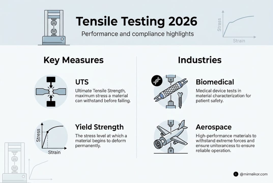
Tensile testing is the controlled application of uniaxial force to a material specimen until it deforms or fractures. The test generates a stress-strain curve that captures how a material responds across its full loading range, from elastic deformation through plastic flow to final failure. That curve is the foundation for quantifying ultimate tensile strength (UTS), yield strength, elongation at break, and elastic modulus, the four properties that drive most structural design decisions.
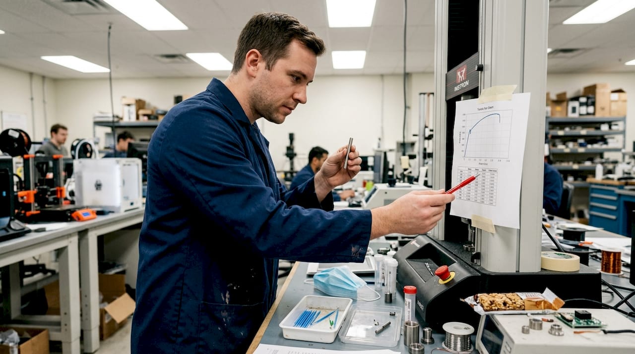
A universal testing machine (UTM) grips the specimen at both ends and pulls at a precisely controlled crosshead speed. Load cells and extensometers record force and displacement simultaneously, feeding data into software that converts raw signals into engineering stress and strain. Standard test conditions specify specimen geometry, gauge length, and strain rate to make results reproducible and comparable across labs.
The key standards your team needs to know:
- ASTM E8/E8M: Metals at ambient temperature, the baseline for most structural alloys
- ASTM F136 / F1472: Ti6Al4V ELI for biomedical implants; tensile testing validates mechanical properties for implant-grade titanium under these standards
- ASTM E21 / ISO 6892-2: Elevated temperature testing for aerospace alloys and turbine components
- ISO 527: Plastics and polymer matrix composites, critical for medical device housings and structural panels
Understanding tensile, compression, and shear testing together gives your team a complete mechanical picture, but tensile data is almost always the starting point for compliance documentation.
When a specimen is pulled beyond its UTS, localized thinning called the necking phenomenon) begins. This is not a defect. It is a predictable material behavior that marks the onset of instability and signals the true load-bearing limit of the cross-section. Recognizing necking on a stress-strain curve tells you whether a material fails gracefully or catastrophically, which is critical information for implant and structural component design.
“Tensile data is not just a compliance checkbox. It is a window into how your material will behave at the boundary between safe operation and failure.”
Exploring mechanical testing methods beyond tensile alone helps R&D teams build a testing strategy that covers fatigue, fracture toughness, and surface mechanics in addition to static strength.
How tensile tests are performed: From sample to result
With the basics established, let’s walk through a real-world tensile test from sample selection to actionable results.
- Specimen design and preparation: Dog-bone specimens are machined or printed to ASTM or ISO geometry. Surface finish, notch-free transitions, and accurate gauge length are non-negotiable. Any machining artifact becomes a stress concentrator.
- Mounting and alignment: The specimen is loaded into grips with precise axial alignment. Even a 2-degree offset introduces bending stress that distorts your modulus measurement.
- Strain rate selection: Quasi-static tests typically run at 1 to 10 mm/min. Faster rates elevate apparent strength in rate-sensitive materials. Your standard specifies the rate; deviating from it invalidates comparisons.
- Data capture: Load cells and clip-on or non-contact extensometers record force-displacement data at high frequency. Digital image correlation (DIC) is increasingly used for full-field strain mapping on complex geometries.
- Result interpretation: The software outputs a stress-strain curve. You read off yield strength (0.2% offset method), UTS, elongation, and modulus. Each value carries a design implication.
For additively manufactured materials, the workflow adds a critical variable: build orientation. SLM Ti64 UTS peaks at approximately 527 MPa with elongation around 32% at optimal volumetric energy density (VED), but modulus and strength shift measurably when print angle changes from 0° to 90°. This is not a minor correction. It can determine whether a printed implant or bracket meets its design load case.
For dental and implant material evaluation, we routinely test specimens in multiple orientations to map the full anisotropic behavior before any design is finalized. Similarly, mechanical and biomechanical surface testing complements bulk tensile data by characterizing surface hardness and adhesion, properties that bulk tensile tests alone cannot capture.
Pro Tip: Always test at least five specimens per condition and report mean plus standard deviation. A single outlier can be a genuine material defect or a test artifact. Five specimens let you tell the difference statistically.
Industry-specific insights: Biomedical, aerospace, and manufacturing
The value of tensile data truly emerges when you look at its impact across specific industries.
Biomedical: Orthopedic implants and spinal fixation devices made from Ti6Al4V ELI must meet ASTM F136 minimum tensile requirements: UTS of at least 860 MPa and yield strength of at least 795 MPa for annealed material. These are not arbitrary numbers. They reflect the cyclic loading environment inside the human body over decades. Bio-interface and integration analysis extends this further by evaluating how mechanical properties at the implant-tissue boundary affect osseointegration and long-term fixation.
Aerospace: Carbon fiber reinforced polymer (CFRP) panels and titanium fasteners must maintain high stiffness-to-weight ratios under thermal cycling and vibrational loading. Printed composite modulus at 0° reaches approximately 1.73 x 10^5 MPa, while 90° samples drop to around 1.06 x 10^5 MPa, a 39% reduction that directly affects structural margin calculations. Aerospace engineers who ignore print angle in additive manufacturing qualification programs are building in hidden risk.
Manufacturing: For high-volume production, tensile testing functions as a statistical process control tool. Batch-to-batch variation in raw material, heat treatment, or forming process shows up in UTS and elongation data before it becomes a field failure.
| Material / Condition | UTS (MPa) | Yield Strength (MPa) | Elongation (%) | Elastic Modulus (GPa) |
|---|---|---|---|---|
| SLM Ti64, optimal VED, 0° | ~527 | ~450 | ~32 | ~114 |
| Wrought Ti6Al4V ELI (ASTM F136) | 860 min | 795 min | 10 min | ~114 |
| CFRP, 0° layup | varies | N/A | ~1.5 | ~173 |
| CFRP, 90° layup | varies | N/A | ~1.0 | ~106 |
Pro Tip: When qualifying a new additive manufacturing process, test specimens from at least three build positions (front, center, rear) and two orientations. Process variation across the build envelope is real and often larger than material-to-material variation.
Avoiding pitfalls: Common artifacts and how to overcome them
Accurate tensile testing is about more than pressing start. Common traps can undermine even the best setups.
The most frequent sources of bad data:
- Grip slippage: The specimen slides in the grips, producing artificially high apparent elongation and a distorted modulus. Use serrated grips with the correct jaw pressure for your material.
- Misalignment: Off-axis loading introduces bending, which inflates apparent modulus and can cause premature failure outside the gauge length. Verify alignment with a calibration specimen before each test series.
- Inconsistent strain rate: Accelerating through yield artificially raises measured yield strength in rate-sensitive alloys and polymers.
- Temperature drift: Even a 10°C ambient shift changes modulus and yield strength in polymers and some light alloys. Climate-controlled test rooms are not optional for precision work.
- Premature fracture outside gauge: If the specimen breaks at the shoulder radius, the result is invalid. This usually signals a machining defect or grip damage.
The necking criterion defined by Considère) is a useful diagnostic: necking should initiate at UTS and progress within the gauge length. If fracture occurs elsewhere, your data is compromised.
| Artifact | Symptom on Curve | Root Cause | Fix |
|---|---|---|---|
| Grip slippage | False elongation plateau | Insufficient grip force | Increase jaw pressure, use serrated grips |
| Misalignment | Non-linear initial modulus | Eccentric loading | Realign grips, use alignment fixture |
| Temperature drift | Batch-to-batch modulus scatter | Uncontrolled environment | Condition specimens 24h at test temperature |
| Out-of-gauge fracture | Low UTS, no necking | Machining defect or grip damage | Inspect specimens, replace grips |
For ongoing quality assurance, reviewing mechanical testing best practices and pairing tensile data with fatigue and wear analysis gives your team a complete picture of how a material performs under both static and dynamic loading conditions.
Pro Tip: Use a non-contact video extensometer whenever possible. Clip-on extensometers add mass and can slip on smooth or coated specimens, introducing the very artifacts you are trying to avoid.
Our take: Moving beyond numbers in tensile testing
We have run tensile programs across biomedical, aerospace, and manufacturing projects long enough to recognize a pattern: teams that treat tensile testing purely as a compliance gate consistently miss the deeper value in their own data. A UTS number tells you whether you passed. The shape of the stress-strain curve tells you why your material behaves the way it does and where the design has room to improve.
The most productive projects we support are those where tensile data feeds directly into design iteration. When an unexpected drop in elongation appears in a new alloy batch, that is not just a rejection trigger. It is a signal pointing toward a processing variable worth investigating. Cross-sector experience matters here. Lessons from aerospace composite anisotropy have directly informed how we approach additive biomedical implant qualification.
We encourage teams to review their case studies and publications as part of their testing strategy planning. Data-driven mechanical property mapping, across orientations, temperatures, and processing conditions, is where tensile testing transitions from a compliance task to a genuine innovation tool.
Unlock advanced tensile testing with Materials Metric
If leveraging tensile testing to its full potential sounds like your next step, here is how you can access expert support.

At Materials Metric, we deliver tensile and mechanical property testing aligned with ASTM, ISO, and GLP/GMP standards, backed by expert interpretation that goes beyond raw numbers. Whether your team needs regulatory documentation for a biomedical device, process qualification for an additive manufacturing line, or batch compliance testing for aerospace components, we function as an extension of your R&D team. Explore our analytical testing methods and advanced material characterization capabilities, then contact us to discuss a testing program tailored to your compliance and innovation goals.
Frequently asked questions
What does tensile testing measure in advanced materials?
Tensile testing quantifies how much stress a material can withstand before breaking and reveals properties like UTS, yield strength, elongation, and modulus. These properties validate implant-grade alloys and structural components against regulatory acceptance criteria.
Why does print angle matter for 3D-printed (SLM) metals in tensile tests?
Print angle affects microstructure and grain orientation, changing tensile strength and modulus significantly. 0° SLM Ti64 delivers higher UTS and stiffness than 90° samples, which is critical for load-bearing additive components.
What are common sources of error during tensile testing?
Grip misalignment, slippage, necking outside gauge length), and temperature fluctuations can all create unreliable or misleading results that invalidate compliance documentation.
How do standards like ASTM F136 and ISO 6892-2 ensure reliable tensile data?
These standards specify sample geometry, test rates, and acceptance criteria, making tensile results comparable across labs and compliant for regulatory submission. ASTM F136 validates Ti6Al4V ELI implant alloys against defined minimum strength thresholds.
What is necking and why does it matter in tensile testing?
Necking is localized thinning that begins after a material reaches its UTS, marking the onset of instability. The Considère criterion defines) when necking initiates, helping engineers identify true material limits and distinguish valid failure from test artifacts.